

 English
  русский
  Español
  Português
Новости отрасли
Bailey Truss Bridge Guide: Panels, Specs, Load Capacity
Контент
- 1 What A Bailey Truss Actually Is
- 2 Where The Bailey Truss Design Came From
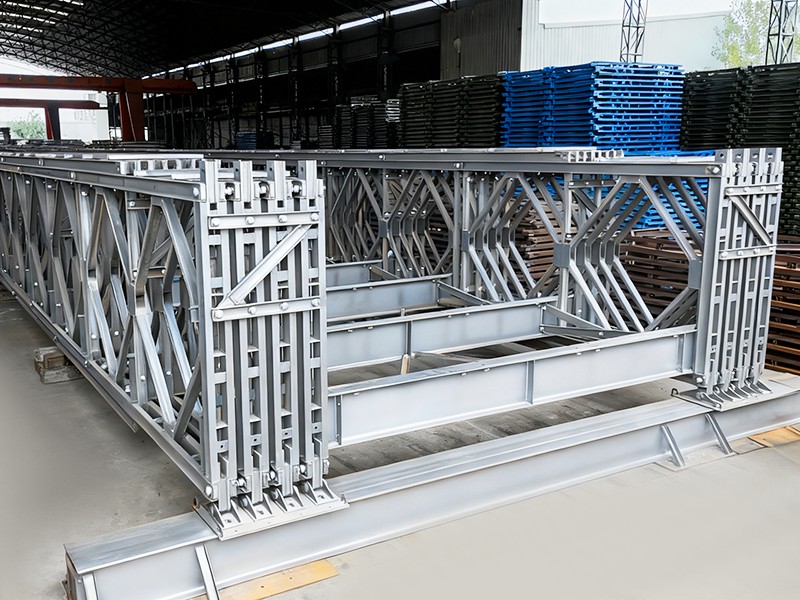
- 3 Core Components Inside A Bailey Truss Panel
- 4 Why Triangulation Makes The Truss Work
- 5 Standard Panel Dimensions And Weight Ranges
- 6 Configuration Types: Matching The Truss To The Load
- 7 Load Capacity And Span Planning
- 8 Deflection, Camber And Site Engineering Notes
- 9 Steel Grade And Corrosion Protection
- 10 How A Bailey Truss Bridge Goes Up On Site
- 11 Service Life And Ongoing Maintenance
- 12 Lifecycle Cost And Economics Compared To Fixed Structures
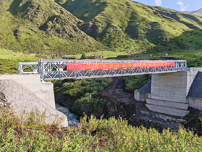
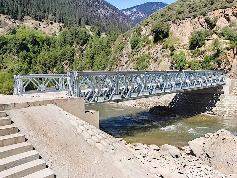
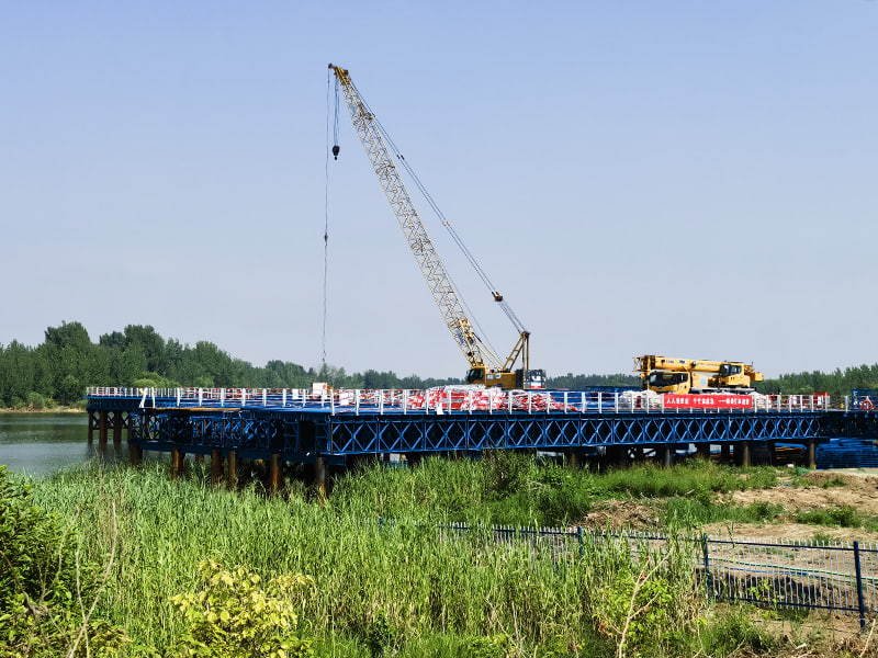
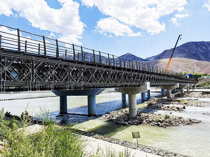
- 13 Where Bailey Truss Bridges Get Used Today
- 14 Frequently Asked Questions
- 14.1 What is the difference between a bailey truss and a bailey bridge?
- 14.2 How long can a bailey truss span without a support pier?
- 14.3 Can a bailey truss bridge carry heavy trucks?
- 14.4 Are bailey truss panels interchangeable between suppliers?
- 14.5 How long does a bailey truss bridge last?
- 14.6 Does a bailey truss bridge need a foundation?
- 14.7 Can a bailey truss bridge be taken down and reused elsewhere?
- 14.8 What causes vibration or bounce on a newly built bailey truss bridge?
- 14.9 Is a bailey truss suitable for railway crossings as well as roads?
- 14.10 How many people are needed to erect a bailey truss span?
What A Bailey Truss Actually Is
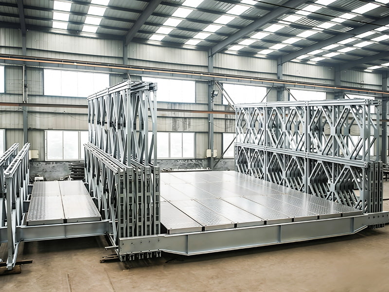
A bailey truss is a prefabricated steel panel bridge component built from triangulated upper and lower chords, vertical posts and diagonal braces, designed to be pinned together on site without cranes, welding or cast foundations. Each panel is 3.048 meters (10 feet) long and roughly 1.4 to 2.15 meters high depending on the manufacturer, and multiple panels combine side by side and story by story to form a girder strong enough to carry vehicle, rail or pedestrian traffic. The system was originally developed for military river crossings, but the same panel logic now underpins most modular steel bridges sold for rural roads, mining haul routes, disaster relief and temporary highway detours.
The defining feature of a bailey truss is interchangeability. Every panel from a given series shares identical pin holes, so a contractor can extend a span, add a second row for extra width, or stack a second story for extra strength using the same stock of parts. That single design decision is why the bailey truss format has stayed in continuous use for more than eight decades while other temporary bridge concepts have come and gone.
In practical terms, a bailey truss answers three questions a project team usually asks first: how fast can it go up, how much can it carry, and can it be reused somewhere else afterward. Because the panel is a standard building block rather than a custom fabrication, all three answers tend to be better than what a site-specific steel or concrete design can offer within the same timeline.
Where The Bailey Truss Design Came From
The panel bridge concept traces back to a wartime requirement for a crossing system that infantry could build under field conditions with basic tools and no heavy plant. The core idea, a repeating triangulated panel joined by a single pin type, solved two problems at once: it removed the need for on-site welding, and it let the same stock of parts be reused across dozens of different span lengths.
What kept the format relevant long after its original purpose faded is the fact that panel logic scales in both directions. A single row of panels handles a footbridge; three rows stacked two stories high, chord reinforced, handles a loaded highway truck. Very few structural systems offer that range from one parts catalogue, which is why civil contractors, mining operators and disaster relief agencies still specify a bailey truss layout today rather than a bespoke steel girder.
| Era | Primary Use |
|---|---|
| Original design intent | Rapid field river crossings, hand assembled with no cranes |
| Post-conflict reconstruction | Replacing damaged civilian road and rail crossings |
| Current commercial use | Rural access, mining haul roads, disaster response, highway detours, pedestrian and utility crossings |
Core Components Inside A Bailey Truss Panel
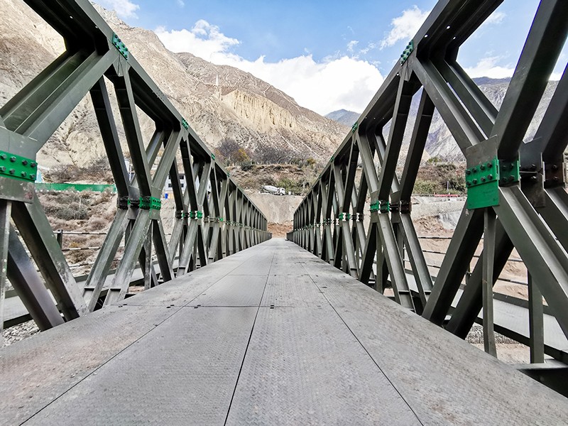
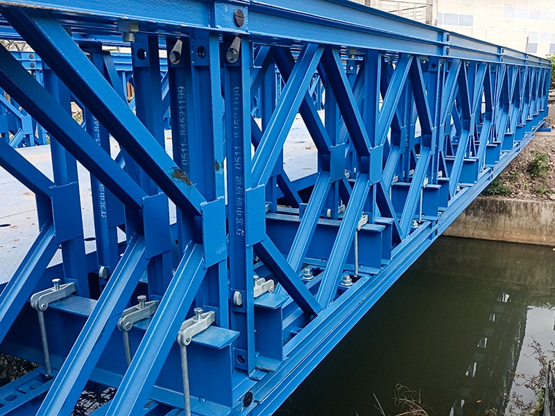
A finished bailey truss bridge is a stack of a small number of repeating parts. Understanding what each piece does makes it much easier to read a supplier's parts list or a site erection drawing.
| Component | Function | Typical Material |
|---|---|---|
| Panel chord | Carries the main tension and compression forces along the span | Double channel steel |
| Vertical post | Transfers deck load into the chords and keeps the panel square | 8 gauge I beam section |
| Diagonal brace | Completes the triangulated pattern that gives the panel its rigidity | Rolled steel section |
| Panel pin | Joins adjacent panels at the male and female lugs | Forged alloy steel, roughly 3 kilograms each |
| Transom | Spans between the two truss lines and carries the deck | Rolled steel beam |
| Sway brace and rakers | Resist lateral wind and vibration loads, prevent side sway | Steel tie rods |
| Chess and stringers | Form the running deck surface for vehicles or foot traffic | Timber or steel chequer plate |
| Bearing and end post | Transfers the full truss reaction into the abutment | Cast or fabricated steel |
On the lower chord of every panel, four beam seating plates hold the transom in position, and two oval holes at the end of the channel accept the sway brace connection. Because the same pin size and hole spacing repeats across the entire panel, a crew can disassemble a bailey truss bridge and rebuild it in a completely different span length using the same inventory, which is the main reason rental fleets are built around this format.
Why Triangulation Makes The Truss Work
The strength of a bailey truss does not come from any single heavy member, it comes from geometry. A triangle is the only polygon that cannot change shape without changing the length of one of its sides, so once the diagonal braces, verticals and chords are pinned into triangles, the panel resists bending without needing a solid steel plate web.
This has two practical consequences that matter for anyone specifying a project:
- Load is shared across every member in the panel rather than concentrated in one point, which is why a bailey truss can flex slightly under a moving vehicle without local failure
- Because the panel is open lattice rather than a solid plate girder, it uses far less steel per meter of span than a solid beam of equivalent strength, which keeps individual panel weight low enough for manual handling
Engineers describe this efficiency using a strength-to-weight ratio, and it is the reason a 300 kilogram panel can, when combined with others in the right configuration, support vehicles weighing many tons.
Standard Panel Dimensions And Weight Ranges
Panel geometry is one of the few things that has stayed almost unchanged across manufacturers since the original British design, which is why parts from different eras and different factories are often still compatible. Reinforced chord panels and double story panels only change the load path, not the base envelope.
| Parameter | Typical Value |
|---|---|
| Panel length | 3.048 m (10 ft), pin hole to pin hole |
| Panel height | 1.45 m to 2.15 m depending on series |
| Panel weight | 270 kg to 349 kg |
| Standard roadway width | 3.27 m single lane, 4.25 m wide lane |
| Panel pin weight | Approximately 3 kg per pin |
| Practical clear span | 6 m to over 90 m with intermediate piers for longer runs |
Because every panel weighs under 350 kilograms, a crew of four to six people can lift and pin a panel by hand, which is exactly what made the format practical for sites where mobile cranes cannot reach. Heavier deck and transom pieces are usually rolled into place on temporary rollers rather than carried.
Configuration Types: Matching The Truss To The Load
The single biggest advantage of a bailey truss system is that load capacity is a building block problem rather than a redesign problem. Instead of engineering a new bridge for every span and axle load, the same panel is repeated in different row and story combinations.
- Single-Single (SS): one row of panels, one story tall, used for light pedestrian or farm access crossings
- Double-Single (DS): two rows of panels side by side for a moderate increase in bending capacity
- Triple-Single (TS): three rows side by side, common on medium span highway crossings
- Double-Double (DD) and Triple-Double (TD): two-story stacking added to double or triple row configurations for longer spans under heavier axle loads
- Reinforced variants (SSR, DSR, TSR): a chord reinforcement member bolted along the top and bottom chord to raise capacity without adding a full extra row
| Configuration | Rows x Stories | Typical Fit |
|---|---|---|
| SS | 1 x 1 | Footbridges, farm and light utility crossings |
| DS | 2 x 1 | Light vehicle rural roads |
| TS | 3 x 1 | Medium span single lane highway sections |
| DD | 2 x 2 | Longer spans with moderate heavy vehicle traffic |
| TD | 3 x 2 | Long span, full highway load, mining haul routes |
Choosing between these configurations comes down to two numbers: the clear span the site needs and the design vehicle or rail load the bridge must carry. As a general pattern, doubling the number of truss rows roughly doubles bending capacity, while adding a second story primarily helps with longer spans where deflection, not raw strength, becomes the limiting factor.
Load Capacity And Span Planning
Most bailey truss bridges built today are designed around standard highway load models such as HS-20, HL-93 or comparable heavy vehicle load cases, and configuration selection is what lets one panel type cover such a wide range of outcomes. A single-single configuration is generally suited to spans up to around 30 meters carrying light traffic, while a chord reinforced double-double or triple-double layout can push usable spans well beyond 60 meters while still carrying full highway loading.
Reported load ranges across current suppliers commonly fall between 30 and 70 tons depending on configuration, span and story count, according to manufacturer product literature. Two practical rules consistently show up in project planning documents:
- Longer spans push a project toward more rows or an added story before they push it toward a different bridge system entirely
- Extremely heavy or oversized vehicles are usually handled by adding chord reinforcement and extra panels rather than by changing the bridge type
For multi span crossings, intermediate piers are simply added at panel-length intervals, which means a bailey truss layout can, in principle, be extended indefinitely as long as pier spacing and soil conditions allow it. Planning teams typically confirm three inputs before finalizing a configuration: the design vehicle weight and axle spacing, the clear span demanded by the crossing, and the ground bearing capacity available for abutments or intermediate piers.
Deflection, Camber And Site Engineering Notes
Two engineering details separate a well-planned bailey truss project from a poorly planned one: deflection control and pre-camber. As span length increases, a truss under moving load deflects more even if it is technically strong enough to carry the weight, and excessive deflection creates a rough ride and long-term fatigue at the pin connections.
To offset this, longer spans are typically built with a small upward pre-camber, meaning the unloaded truss sits slightly higher in the middle than at the ends, so that under full traffic load it settles to a level, comfortable profile rather than sagging visibly. Site teams also check three supporting details before opening a crossing:
- Bearing pad condition and levelness at both abutments
- Correct pin insertion direction and full engagement at every panel joint
- Sway bracing torque, since loose lateral bracing is the most common cause of vibration complaints on a new installation
Steel Grade And Corrosion Protection
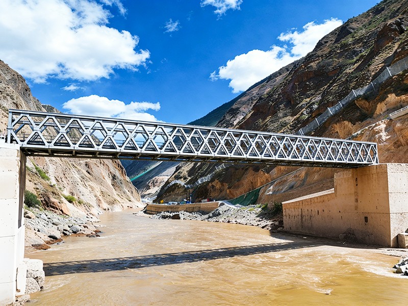
Chords and posts are typically rolled from high-tensile low-alloy steel, with panel pins forged from alloy steel such as 30CrMnTi for wear resistance at the connection points. Because a bailey truss is expected to sit outdoors, often near water, corrosion protection is not an afterthought, it is part of the base specification.
Two coating approaches dominate current production. Hot-dip galvanizing corrodes at roughly one thirtieth the rate of bare steel in the same environment and is widely documented as delivering multiple decades of maintenance-free service life on outdoor steel structures. The alternative is an inorganic zinc-rich primer system, which gives strong protection at lower shipping weight but generally needs a repaint cycle sooner than a full hot-dip coating. Pins and smaller fasteners are almost always galvanized separately, since their small cross section makes them the fastest part of the assembly to corrode if left uncoated.
For coastal, marine or heavy de-icing salt environments, project specifications increasingly call for a duplex system, meaning a galvanized base layer topped with a compatible paint coat, since salt exposure accelerates zinc consumption noticeably faster than a typical inland site.
| Coating | Best Suited Environment | Relative Service Life |
|---|---|---|
| Hot-dip galvanizing | General outdoor, inland and moderate humidity | Long, often decades before first maintenance |
| Zinc-rich primer paint | Lighter duty, cost-sensitive projects | Moderate, repaint cycle required sooner |
| Duplex (galvanize plus paint) | Coastal, marine, heavy salt exposure | Longest, combines both protection mechanisms |
How A Bailey Truss Bridge Goes Up On Site
The launching sequence is the other reason this system remains popular for emergency and remote-site work: it does not depend on heavy cranes reaching the crossing point.
- Survey the crossing and confirm clear span, bank height difference and soil bearing capacity at both sides
- Prepare and level abutments or bearing pads on both banks, checking that they are square to the intended centerline
- Assemble the first panels on rollers on the near bank, pinning chords, posts and diagonals into a complete truss section
- Add transoms and sway bracing as each new panel is pinned in, keeping the growing structure laterally stable
- Launch the assembled truss nose forward across the gap using rollers or a launching nose, adding panels from the near bank as the front end advances
- Once the leading end reaches the far bearing, lower the completed span onto both abutments and remove the rollers
- Install decking, chequer plate or timber chess, then check pin torque and bracing before opening the crossing to traffic
- Carry out a final walk-through inspection covering bearings, pins, bracing and deck fasteners before signing off the crossing for use
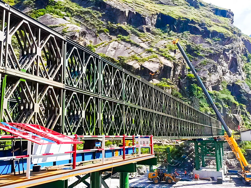
Because every panel is under 350 kilograms and every connection is a pin rather than a weld, a trained crew can erect a moderate span bailey truss bridge in a matter of days using hand tools and a small support crane for the deck components, rather than the weeks typically needed for a cast concrete crossing.
Service Life And Ongoing Maintenance
Although the bailey truss format was originally built for temporary military use, properly maintained installations routinely stay in service for several decades, including on public roads carrying regular traffic. Field studies on hot-dip galvanized steel bridge components have recorded structures remaining largely maintenance-free for 50 years or more in typical inland environments.
| Check | Frequency | What To Look For |
|---|---|---|
| Pin and bolt tightness | After first season, then annually | Play or movement at panel joints |
| Coating condition | Annually | Scratches, bare metal or rust bleed |
| Drainage paths | Seasonally | Standing water against the lower chord |
| Deck fasteners | Annually | Loose chequer plate or worn timber chess |
None of these tasks require specialized certification bodies or heavy equipment, which keeps lifecycle cost low compared with a permanent structure of similar span.
Lifecycle Cost And Economics Compared To Fixed Structures
The economics of a bailey truss project rarely come down to steel tonnage alone. Three factors usually decide whether a panel bridge or a fixed structure makes more sense for a given crossing:
- Timeline: a panel bridge can typically be designed, delivered and erected far faster than a poured foundation and steel or concrete girder structure
- Reusability: panels can be recovered and redeployed at a different site once a project or emergency need ends, which a fixed structure cannot offer
- Site access: locations without room for large plant or crane access favor a system that erects with hand tools and small support equipment
For crossings that are genuinely permanent and centrally located, a fixed structure often wins on long-run maintenance simplicity. For anything temporary, remote, or subject to changing traffic patterns, the ability to relocate a bailey truss later is frequently the deciding factor rather than upfront material cost.
Where Bailey Truss Bridges Get Used Today
The application list has grown far beyond the system's original military role. Common current uses include:
- Rural and forestry road crossings where a permanent structure is not yet justified
- Mining and quarry haul routes needing high load capacity with the option to relocate the bridge later
- Disaster response and flood recovery, replacing washed-out crossings within days
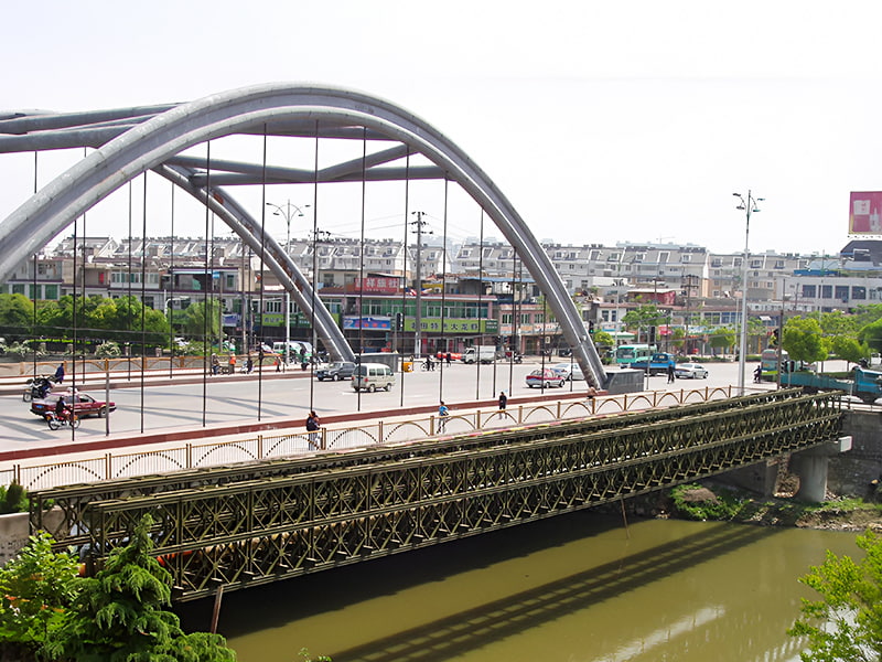
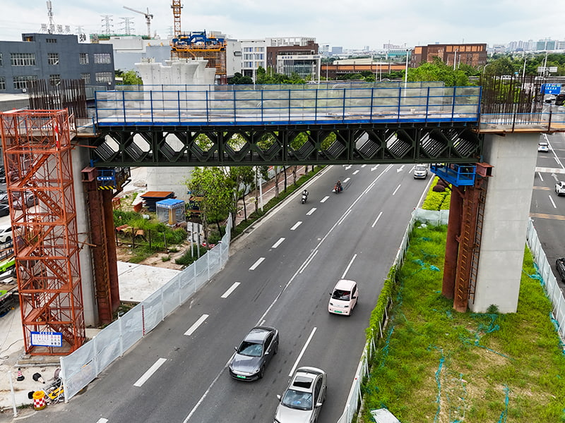
- Detour bridges while a permanent highway structure is being rebuilt nearby
- Pedestrian and utility crossings, gantry supports and temporary trestles on active construction sites
- Pipeline and cable crossings where panels double as a support trestle rather than a roadway
This range of use cases is exactly why panel stock, rather than a single fixed bridge design, has become the standard way suppliers think about the bailey truss product line: the same inventory serves a farm track one month and a highway detour the next.
Frequently Asked Questions
What is the difference between a bailey truss and a bailey bridge?
The truss is the triangulated panel structure that carries load; the complete bailey bridge also includes the deck, transoms, bracing and abutment connections built from that truss.
How long can a bailey truss span without a support pier?
Single span layouts commonly reach 30 to 60 meters depending on configuration, with chord reinforced double or triple row layouts able to exceed that range before an intermediate pier becomes necessary.
Can a bailey truss bridge carry heavy trucks?
Yes. Adding rows, an extra story or chord reinforcement raises capacity, and configurations rated for standard highway load models such as HS-20 or HL-93 are common in current manufacturer specifications.
Are bailey truss panels interchangeable between suppliers?
Panels built to the same standard pin spacing and hole pattern, such as the widely used 321-type geometry, are generally interchangeable, which is why many rental fleets mix stock from different production runs.
How long does a bailey truss bridge last?
With hot-dip galvanized components and basic upkeep, several decades of service is realistic, and some installations have been documented remaining largely maintenance-free for over 50 years.
Does a bailey truss bridge need a foundation?
It needs level, stable bearing points on each bank rather than a full foundation, which is a major reason it can be deployed much faster than a cast-in-place structure.
Can a bailey truss bridge be taken down and reused elsewhere?
Yes, this is one of the format's core advantages. Panels are pinned rather than welded, so a complete truss can be disassembled and re-erected at a different span length or location using the same stock.
What causes vibration or bounce on a newly built bailey truss bridge?
Loose sway bracing or pin connections are the most common cause. Retorquing bracing and confirming full pin engagement usually resolves noticeable movement.
Is a bailey truss suitable for railway crossings as well as roads?
Panel bridges have been used for provisional rail crossings, though the configuration, decking and bearing details differ from a roadway installation and are engineered separately for rail loading.
How many people are needed to erect a bailey truss span?
A typical crew of six to ten people can erect a moderate span using hand tools, since individual panels weigh under 350 kilograms and connections are pinned rather than welded.

Мы оперативно реагируем на все международные запросы и при необходимости оказываем техническую поддержку.
Продукт Категория
Мост Бейли/Модульный мост Модульный стальной мост Пешеходный мост Модульный трубный мост Ферменный мост Стальная конструкцияКонтакт Мы

+86-511-84522866
+86-13921582699

zhwm@zjql.com

Здание 1,83#, Новый город Даньту, улица Яньцзян, район Даньту, Чжэньцзян, Цзянсу, Китай
Авторские права © Jiangsu Zhonghai Bridge Equipment Co., Ltd. Все
Права
Сдержанный
